Baynoonah Tunnel, UAE
ESC carried out the design calculations on behalf of the Main Contractor and submitted them for approval to the Client (Abu Dhabi Department of Transport) and their Consultant (Parsons). All designs were to be as per the British Standards.
SHEET PILE RETENTION SYSTEM FOR AL RAS AL AKHDAR AND BAYNOONAH STREET
UPGRADING AND TRAFFIC IMPROVEMENT PROJECT
Introduction
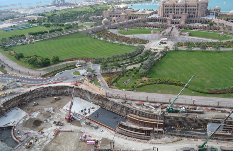
In the recent years, Abu Dhabi has witnessed huge growth in demand on construction and development due to constant increase in cities population and infrastructure demands. Abu Dhabi Department of Transport (DoT) is carrying out various road development works in Abu Dhabi and a strategic decision was made to construct a road tunnel, widen Baynoonah Street and also carry out various landscaping works on the Baynoonah Street, Al Ras Al Akhdar road and in front of the Emirates Palace. A U-shaped road tunnel 25m wide and extending to a depth of 10.5m, was proposed to be built on the Al Ras Al Akdar road. Due to the close proximity of the proposed tunnel to tall structures, a temporary retention system was proposed to be built to facilitate the tunnel construction.
ESC carried out the design calculations on behalf of the Main Contractor and submitted them for approval to the Client (Abu Dhabi Department of Transport) and their Consultant (Parsons). All designs were to be as per the British Standards.
Site Stratigraphy
In general, the overburden soils at site consisted of a 2m thick loose gravel fill followed by loose to medium dense silty sand to about 9m depth. This is followed by dense to very dense silty sand, until bed rock (Calcarenite) is encountered at 11m depth. However depth of bed rock varies consistently and is as shallow as 6m at some locations.
Sheet Pile Retention System
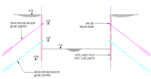
The original design was to build a secant pile wall. However, ESC managed to demonstrate to the client and the consultant that a sheet pile retention system is faster, cheaper and technically sound solution. The proposed embedded steel sheet pile solution was adopted. Large parts of the retaining wall needed to be supported by one and/or two levels of ground anchors with a continuous waling beam.
Due to the sloping nature of the excavation, retaining wall conditions were constantly changing along the length of the wall. The analysis therefore had to be done incrementally, taking design cross sections for each section of the tunnel. Modeling was performed using an effective stress analysis based on BS8002, using the analysis software ReWaRD. The design of the sheet pile system was performed in accordance with the requirements of BS5950. Anchors were designed based on BS8081, which is a working load design standard.
Construction
Installation of the sheet piles was carried out by vibrating the sheet piles to required level with a vibro hammer mounted on a 50T crawler crane.

Layout showing the tunnel alignment and neighboring structures.

Cross section illustrating the sheet pile retention system with 2 levels of ground anchors
Due to the varying depth of hard stratum (depth of bed rock) pre-drilling was carried out to facilitate driving of sheet piles at some locations.
The total length of the temporary sheet pile retaining wall was 790m. Sheet piles of different configuration and length were used to suit the site conditions and the design requirements. The type of sheet piles installed included CR13-575, CR13-600, NSPIIIw and FSPIV with lengths varying between 9.5m and 15m, which correspond to a total tonnage of approximately 1,400T (1,463 nos).
Ground anchors were installed using a horizontal hydraulic drilling rig. The capacity and no. of levels of the ground anchors varied with the depth of excavation. A total of 311 anchors were installed with capacities ranging from 400kN (for shallow excavation) to 1,000kN (for deeper excavation, 10.5m depth).
Waling beams were installed to secure a continuous support of the Retaining Wall. For the Waling beam UPN 300 with a section modulus of 535 cm3/m was used with a total tonnage of approximately 94 T.
Project Photos


